EZB-PM I. Traction Mobile Rectifier Substation
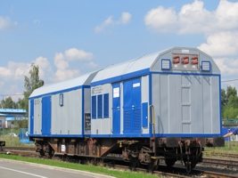
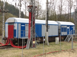
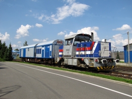
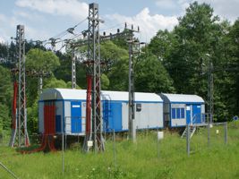
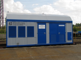
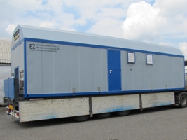
This traction mobile rectifier substation is designed to be used in 2 – 3 kV DC/IT electric traction system to supply overhead contact lines. The traction-substation equipment is installed in two steel containers, which can be, as necessary, transported on a railway flat wagon or using a road truck. In the place of connection to the supply, containers can be installed on a hard area (for example, concrete panels) using steel feet, or they can remain on a railway wagon. The traction substation comprises two containers marked as the K 22 kV container and K 3 kV container.
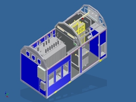
K – 22 kV Container
The 22 kV container contains a 22 kV input distribution point. The main part of the distribution point comprises a metal enclosed, SF6-insulated, 22 kV switchgear and controlgear having five fields, where two fields are incoming-feeder, other two fields are outgoing-feeder (leading to the traction transformer and to the own consumption transformer) and one field designed for electric work metering. Terminals from the 22 kV AC distribution network can be connected to incoming-feeders of the 22 kV switch-gear and control-gear via input bushings using cross-wire suspensions or cables. Input bushings are fixed to the container front wall so that they do not extend the clearance profile to prevent damages and losses in transport. The distribution voltage of 22 kV AC can be conducted to incoming-feeder of the 22 kV switchgear and controlgear by cables through bushings being installed in a container side wall (if a container is placed on a railway wagon) or through bushings being installed in a container bottom wall (in case of a container resting on feet). The 22 kV distribution point includes the station-service transformer having an installed capacity of 50 – 100 kVA, and the main station-service switchboard. The station-service switchboard contains main fuses of fallback circuits (charger, emergency lighting, ventilation system), and auxiliary circuits (heating, other electrical installations.) The switchboard also contains the 20 kVA isolating transformer for the stand-by electricity supply from the 3 × 400 / 230 V AC distribution network.
The biggest part of the 22 kV container is the sealed, oilimmersed type traction transformer having a emergency oil leakage sump. The transformer rated capacity is 5,3 MVA.
The transformer is connected by HV cables leading from the outgoing-feeder of the 22 kV switchgear and controlgear to connectors of the traction transformer primary (input) side. The transformer secondary (output) side is connected to the 3 kV container by HV cables with connectors. Connections between containers with low voltage control and feed circuits are carried out using industrial connectors of various types – quick coupling and non-interchangeability.
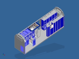
K – 3 kV Container
The 3 kV container is connected to terminals from the traction transformer using HV cables with connectors. In the 3 kV container, the voltage is conducted from the connector to the cabinet-type traction rectifier having forced air-cooling. This rectifier is a twelve-pulse type with a rated current of 1 500 A and the VI class of the overload capacity according to EN 50 328.
The negative terminal of the rectifier is connected to the switchboard of return cables, where the voltage ground-fault protection, disconnector of the traction substation negative terminal, and connectors to connect the return circuit to rails are placed as well. The rectifier positive terminal is connected to the traction reactor and on disconnector of postitive terminal.
The cell of traction reactor is equipped with ventilation fans to remove any waste heat. Cables leading from the positive terminal are connected to the 3 kV DC switchgear and controlgear. Four customized functional units of the EZB-N (type of the standard metal enclosed, air insulated, 3 kV switchgear and controlgear made by EŽ Praha) are used. In outgoing-feeders, withdrawable parts (chariots) with high-speed circuit-breakers are placed. Each outgoing-feeder is equipped with a digital protector, which also controls the whole outgoing-feeder (PLC* + protection). Outgoingfeeders are connected to the overhead contact line via HV cables with connectors.
Just opposite the rectifier, the station-service switchboards and control switchboards are placed. The station-service switchboard comprises the 400 / 230 V AC switchboard, 110 V DC switchboard, and another 110 V DC switchboard with batteries and a battery charger. The control switchboards comprises the switchboard for the remote control system, switchboard for the checking and controlling system and local regulating system, switchboard for the signal No. 50 (pantograph pull down) and coupling of feeders.
Basic Characteristics of 3 kV DC Traction Rectifier Station in Transportable Container
- Simple and well-arranged technical design through the use of well-proven experience resulting from technologies employed in many transportable traction sub stations
- At the client’s option, it is possible to produce an alternative of a traction substation station having a higher capacity using a combination of various types of containers (variability of solutions)
- Short lead time from the time point, when client’s specifications are put more precisely, and a definite order is issued
- EŽ Praha provides the entire production in their own production center.
- Client’s option to carry out partial acceptance tests in the production center.
- Size of traction substation is minimized due to the use of advanced technologies
- When used as a stationary type, this traction substation is advantageous in terms of space-consumption and costeffectiveness
- Transport variability enables to haul this traction substation in an easy way by railway and road as well
- Possibility to use this traction substation as a supply station or switching station
- Variability of power connection to HV input and output sides (overhead or cable line)
- Rapid and easy site installation of HV and LV cable connections between containers using connectors
- Rapid and easy putting of the traction substation into service – from the time point of delivery through installation
- Traction substation is fire protected by the automatic fire extinguishing system using the FE-36 gas extinguishing medium
- Traction substation is protected against trespassing by the IAS (Intrusion Alarm System)
- Simple and easy operation by means of the local control system using a touch screen
- Possibility to operate the traction substation via the integrated RCS (Remote Control System)
- Possibility to use the metering for invoicing on the HV side by means of officially authenticated and calibrated metering transformers
- Possibility of power supply from an extraneous LV service line via an isolating transformer
- Easily variable mounting and putting into operation of feeders coupling
- Possibility to use the mobile signal No. 50 “pantograph pull down”, which is an inseparable part of this traction substation
- Easy connection of the internal earth connection of containers, which is brought out in two points to an external earthing system

